Secrets of the Big Dig
Photographs for a book proposal by Don Eyles
Becauze my status was unofficial I had the freedom to explore wherever my curiosity led me and to photograph scenes that I would have been unable to access if I had been "on assignment." Many of the photographs are taken at night, when sites that were gray pits by day seemed to glow in their own secret light.
This sample is drawn from more than 4000 images made between 1993 and 2005. Most were taken in the 6x9 cm. format using Fuji cameras. A negative of that size provides ample resolution to support high-quality reproduction in a book of photographs.
A far more comprehensive selection of the photographer's Big Dig photos is HERE (opens in separate tab).
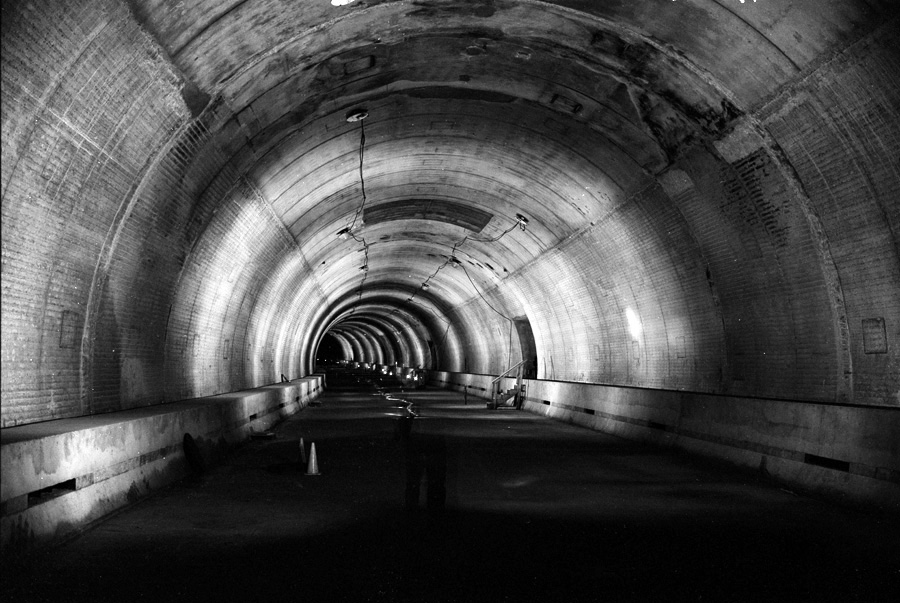
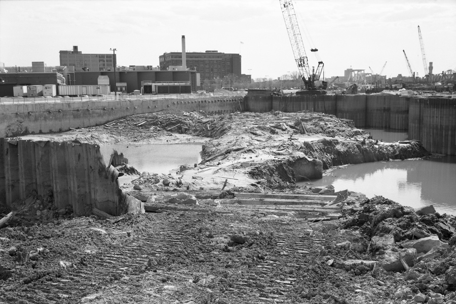
TWT9404170105
TWT9404170204
Ted Williams Tunnel, June 6, 1993
It was Sunday, with the tunnel utterly dark and the ventilation system turned off. The photo was made (with the assistance of Michelle Leger) by leaving the camera's shutter open, and firing a flash at intervals as I walked along the tunnel. At the center, just below the shipping channel, we distinctly heard the large marine engine of a ship or tug passing from east to west above us.
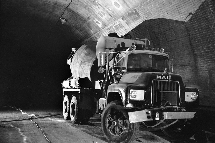
Steel tunnel sections were prefabricated at Bethehem Steel in Baltimore, towed to Boston, and sunk into trenches prepared by dredging. Concrete was then added. Conveniently, a cement-mixer truck was built into the tunnel in Baltimore.

TWT9412180131
TWT9306062A06
TWT9309065B02
Ted Williams Tunnel:
Connection to Seaport Access Road
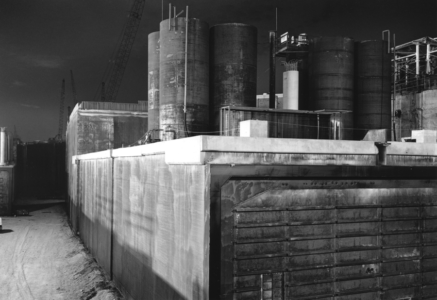
Above left: A round, slurry-wall cofferdam about 300 feet in diameter was the node where the Tunnel connected to the Seaport Access Road through South Boston. (Photo June 6, 1993.)
Above right: Vent Building No. 6 was constructed within the cofferdam. (Photo Dec. 18, 1994.) The recessed portion of the cofferdam wall, visible in both photographs, will be knocked out to allow the roads to connect.
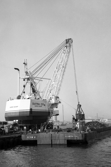
Left: dredge working in Boston Harbor, also visible above-left in background. (Photo Sept. 6, 1993.)
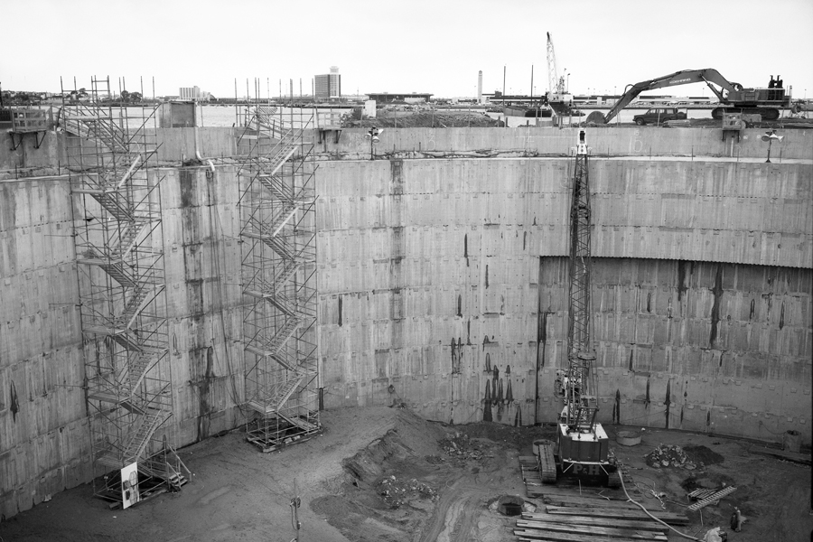
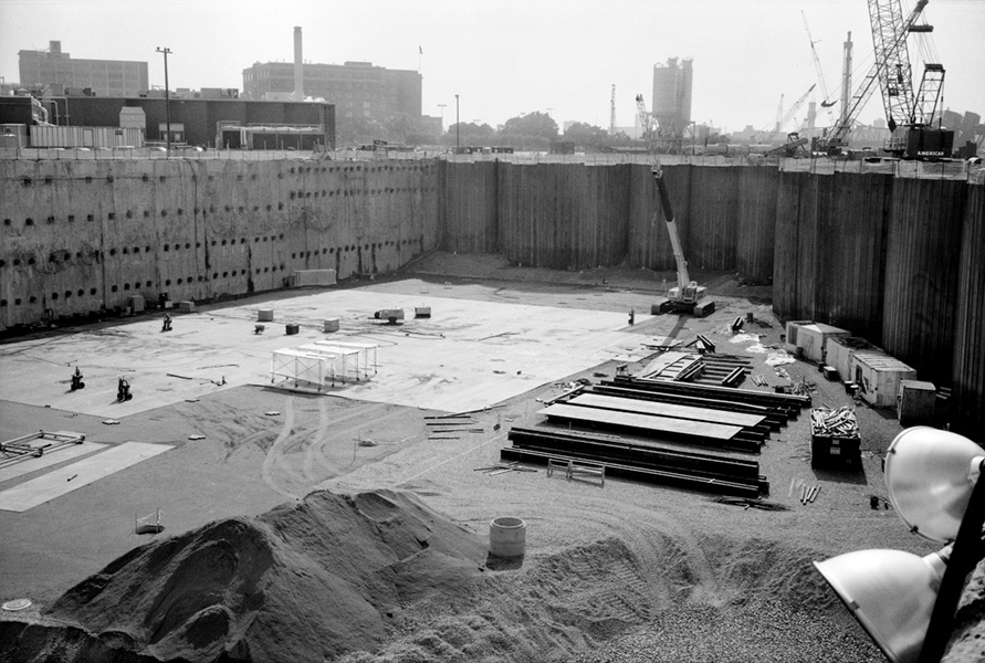
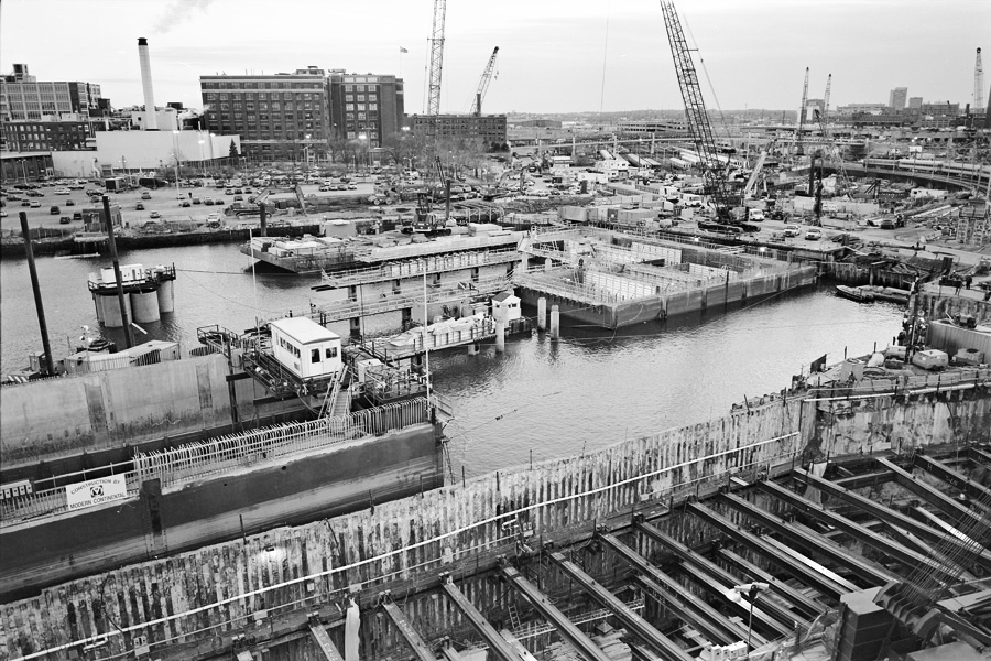
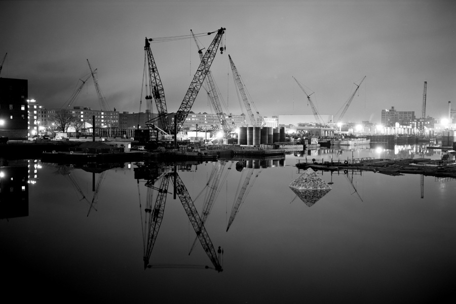
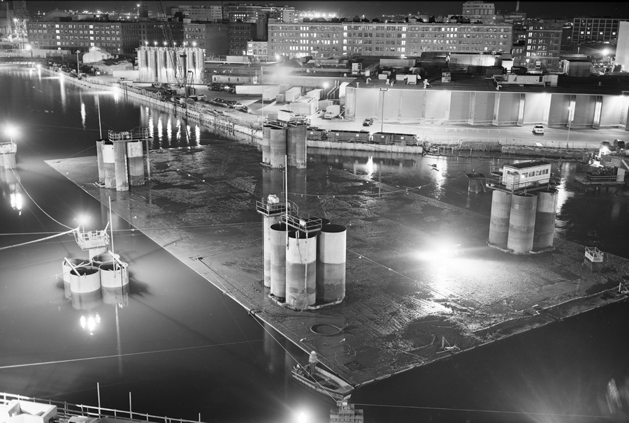
CB9704272A03
Excavating the Casting Basin
April 27, 1997
To connect I90 to the Ted Williams Tunnel requires the highway to pass under an arm of Boston Harbor known as the Fort Point Channel, an operation complicated by tunnels carrying the Red Line subway tracks that run lengthwise through the Channel. The solution is to create a large excavation on the east side where tunnel sections will be fabricated.
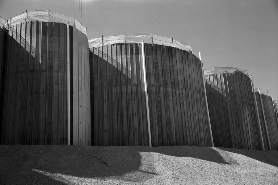
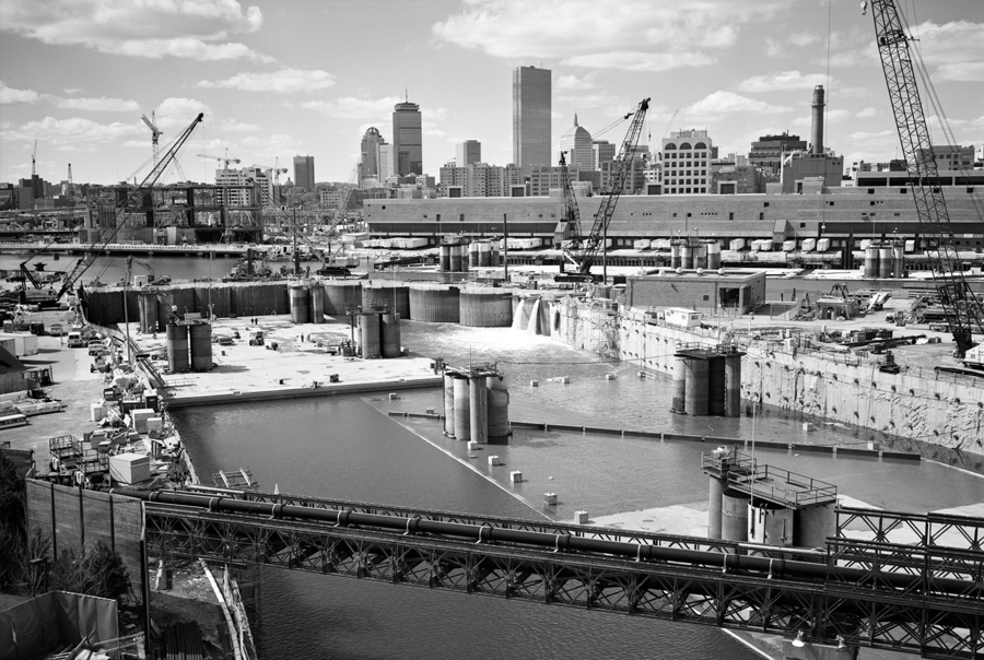
CB9707063A01
Casting Basin: Cofferdams
July 6, 1997
The Casting Basin is separated from the Fort Point Channel by cellular cofferdams filled with gravel. When the tunnel sections are complete the Basin will be flooded, the cofferdams will be removed, and the tunnel sections will be floated into position and sunk onto footings prepared by divers.
CB9708003B02
Casting Basin Excavation Complete
August, 1997
Casting Basin excavation is complete and steel plates are being laid down that will become part of the first, eastbound tunnel section (EB1).
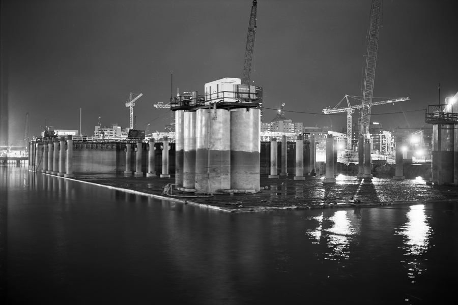
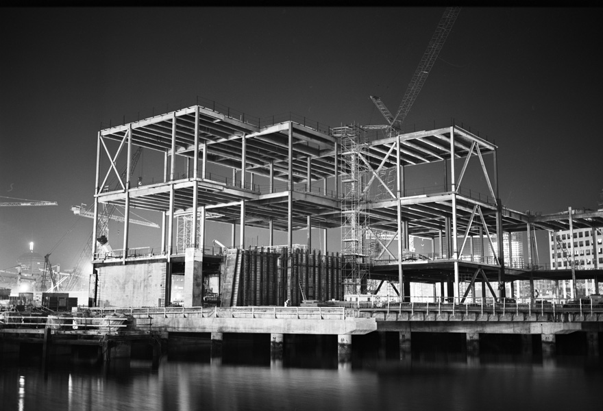
CB9811050203
Casting Basin:
Tunnel Sections Under Construction
November 5, 1998
Here — in a photograh taken from the roof of the photographer's building — the first four tunnel sections are under construction. In the background, the first eastbound and westbound sections (EB1 and WB1) carry columns that will support Dorchester Avenue as it spans the Fort Point Channel, and superstructures that will form part of Vent Building 1, near South Station. In the foreground are the second eastbound and westbound sections (EB2 and WB2).
CB9910030405
Fort Point Channel
October 3, 1999
Tunnel section WB1 complete in the Casting Basin. The vertical cylinders are trim tanks used to adjust the orientation of the tunnel box when it is floating.
FPC0001090504
Fort Point Channel
January 9, 2000
Cofferdams have been removed and the Casting Basin is open to the Fort Point Channel. Tunnel section EB1 has been brought to the surface and is being moved towards its intended position on the opposite side of the Channel.
CB0003040602
Fort Point Channel
March 4, 2000
The Casting Basin is open to the Fort Point Channel. Tunnel section WB1 has been brought to the surface and is being moved to its intended position on the opposite side of the Channel.
SB0003101601
Fort Point Channel
March 10, 2000
Tunnel section WB1 is moving into position between Ramp D (foreground), which connects directly with tunnel section WB2, and tunnel section EB1 (background), now in its permanent position. Sections EB1 and WB1 will together provide the foundation for Vent Building No. 1. (Photo taken from roof of the U.S. Post Office.)
SB0009200306
Vent Building No. 1 Under Construction
September 20, 2000
Only six months after placement of the tunnel sections that provide its foundation, framing of the large vent building is almost complete. Columns seen in previous photographs atop tunnel sections EB1 and WB1 are visible here, ready to support the reconstructed Dorchester Avenue crossing of the Fort Point Channel.
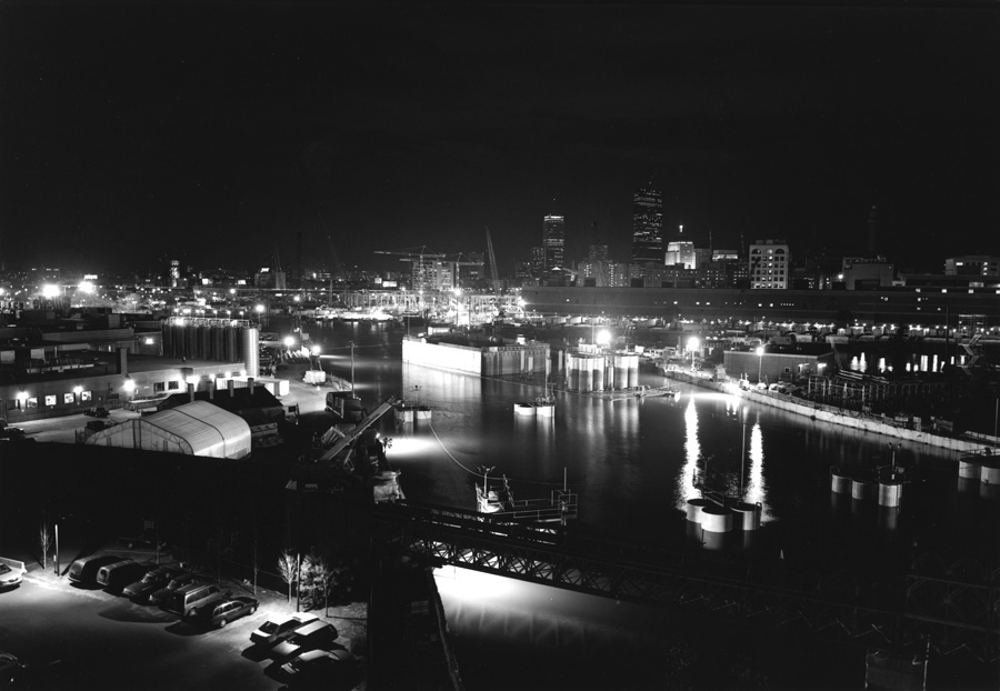
FPC0011041008
Fort Point Channel
November 4, 2000
Pyramid in foreground was launched by the artist in 1998, the first in a series of floating sculptures launched into the Fort Point Channel. The Casting Basin, which at this date is open to the Channel, is in the background beyond the large crane.
CB0103250207
Filling the Casting Basin
March 25, 2001
Water is being pumped into the Casting Basin, after which the cofferdams that separate the Basin from the Channel will be removed and the two remaining tunnel sections (EB3 and WB3) will be floated into position.
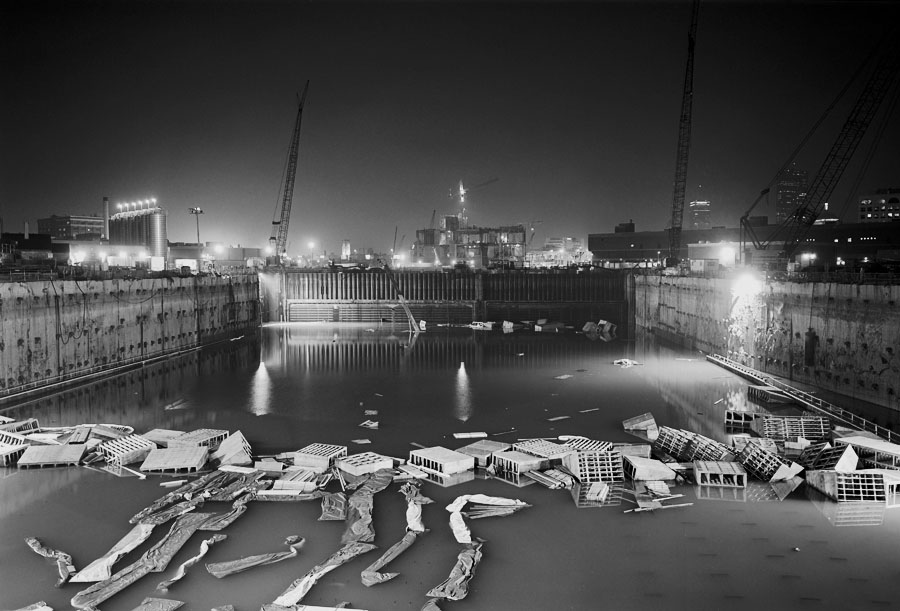
CB0109231301
Casting Basin Flooded
September 23, 2001
The seal under the first westbound tunnel section has failed, alloowing seawater into the excavation behind Vent Building No. 1 on the far side of the Fort Point Channel. Fearing the hydraulic pressure may displace the installed tunnel sections, engineers have allowed water to flow through the tunnel into the Casting Basin.
FPC0104270604
Fort Point Channel
April 27, 2001
Second eastbound tunnel section being winched into position in Fort Point Channel. Photograph taken from upper level of Vent Building 1, then under construction.
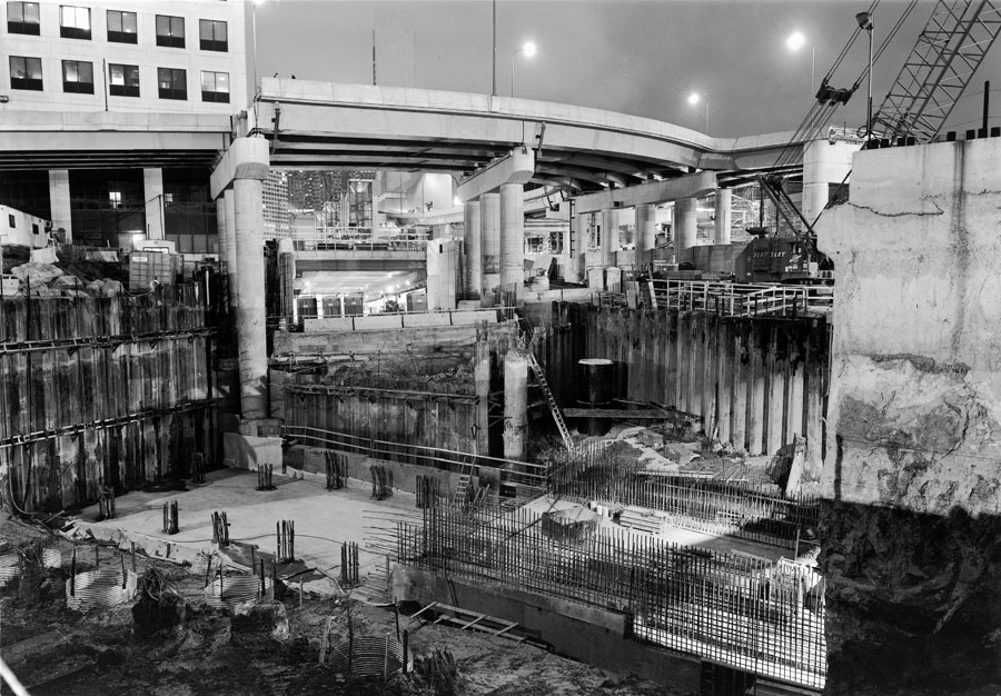
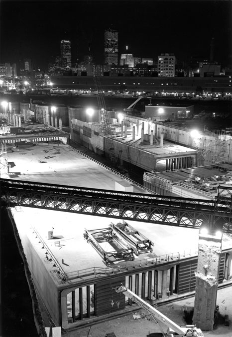
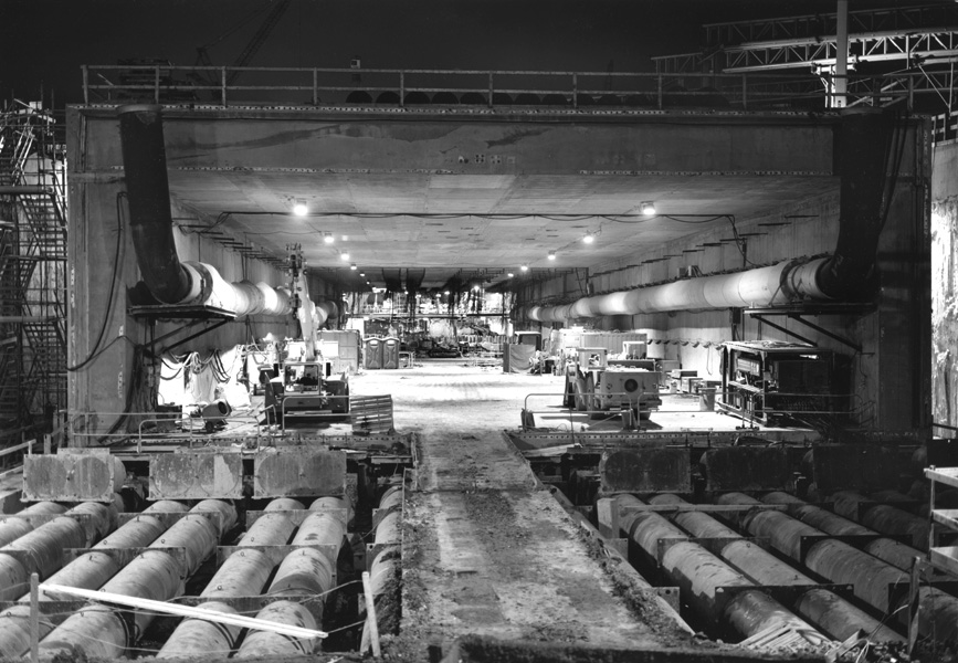
SB0011040907
South Bay Nexus
November 4, 2000
The complex intersection behind South Station, the junction of I90 and I93, takes shape. The vertical spikes at lower-left are tie-downs meant to resist the tendency of the buried highway to "float" upwards. The lighted opening at center leads to the tunnel through downtown; above it is visible the South Station bus terminal.
SB0011040606
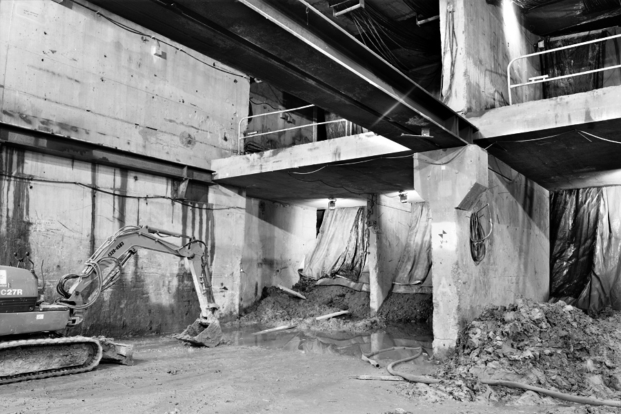
SB0006030903
South Bay Jacking Pit
November 4, 2000
It is also necessary for the new I90 alignment to pass under the railroad lines serving South Station. It is a groundrule that there shall be no interruption of rail service. The solution is to freeze the ground under the tracks to increase its bearing strength, and then to force a tunnel section through the soil.
The tunnel section is moved horizontally by large jacks, while the frozen soil at its leading end (left) is excavated.
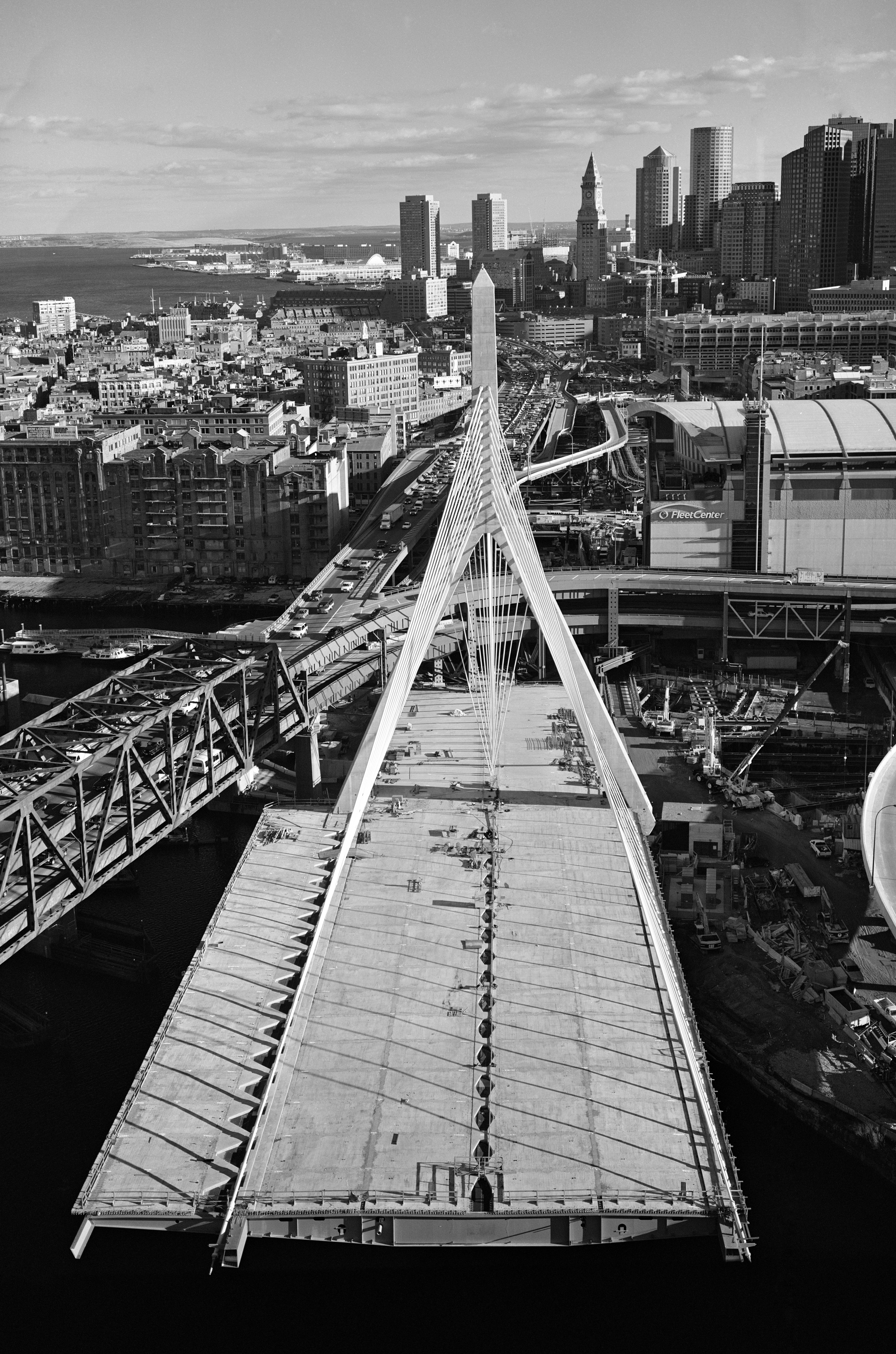
ZB0102260401
ZB0102260505
Zakim Bridge
View from the North Tower
February 26, 2001
These photographs were taken on a Monday afternoon at a time when crews were working on the bridge deck. When I asked the person in charge whether I would be in the way if I climbed the tower, the answer was, "How's your heart?" Access to the top of the tower was by means of an open stairway the equivalent of 25 storys high, with work platforms at the "crotch" and "summit" levels.
The Zakim Bridge roadway, from south to north, rises by about 90 feet between the towers. Thus the peak of the south tower lies below the horizon in this view from the extreme top of the north tower.
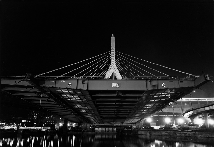
ZB0011030808
Zakim Bridge
November 3, 2000